Simon's Game Using Microcontroller
Assembly, C++ | Embedded Systems
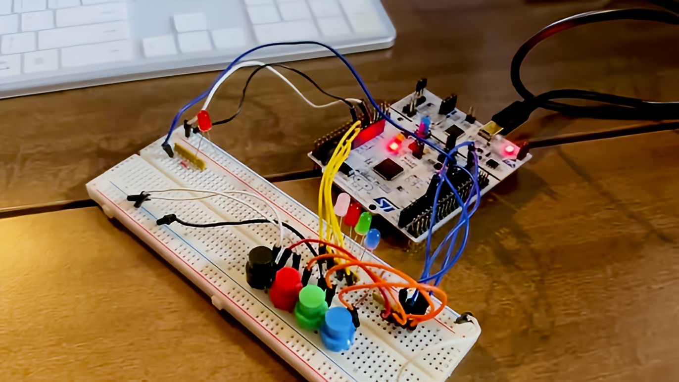
A View of the Project with STM32 Microcontroller and Push-buttons, LED Indicators Connected to the Breadboard
For this individual design project, I designed and implemented a Simon-style memory game on the STM32F103RB microcontroller. Inspired by the classic LED memory challenge, the project tests a player’s ability to recall and reproduce sequences of flashing LEDs using physical buttons. The difficulty ramps up to 10 rounds, with increasing sequence lengths and limited response time.
Tools Used
Programming

C++ | Assembly
Behind the Build: A Visual Story
Top-Down View of Project
This top-down view displays the full hardware setup of the Simon Game implemented on the STM32F103RB Nucleo-64 microcontroller. Four LEDs are connected to GPIO pins PA0, PA1, PA4, and PB0, and are arranged to visually represent the game's output sequence. Each LED is paired with a corresponding push-button (PB4, PB6, PB8, PB9), allowing users to replicate the LED pattern during gameplay. The wiring is carefully routed to ensure clean voltage paths, correct pull-up configurations for button inputs, and clear visibility of the connections for debugging and demonstration purposes. The central placement of the Nucleo board provides a balanced and accessible layout, enabling smooth user interaction while reflecting thoughtful hardware planning and GPIO mapping.

STM32F103RB
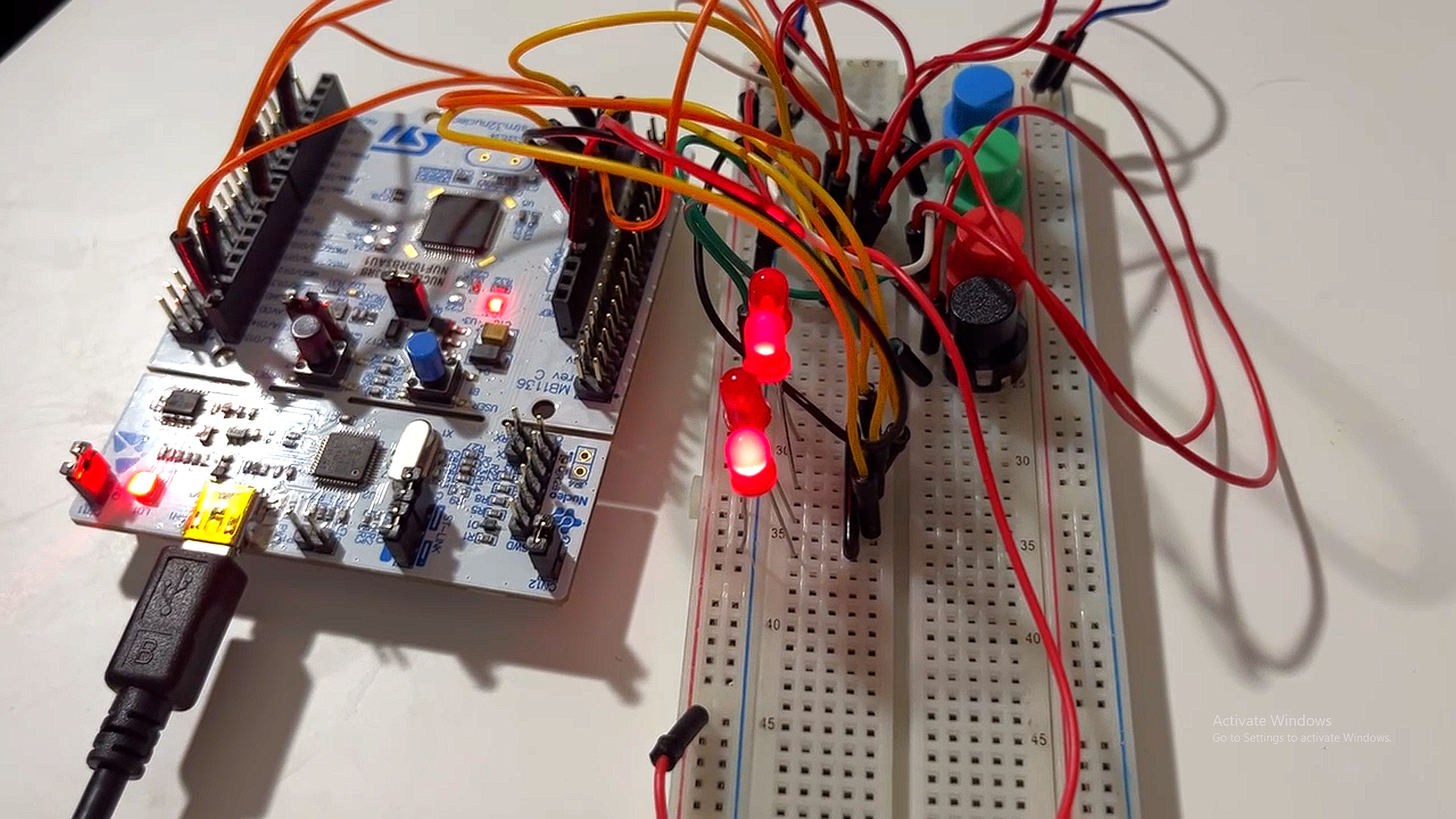
At the heart of the build is the STM32F103RB Nucleo-64 development board, which serves as the main processing unit for the Simon Game. It is responsible for generating LED sequences, handling button inputs, and managing game logic in real time. The board features a 32-bit ARM Cortex-M3 core, enabling responsive performance even with precise timing constraints such as user input timeouts and LED flash durations. GPIO pins on ports A and B are manually configured via register-level Assembly and C code, allowing low-level control over each LED and button. The board is powered and programmed via USB using an onboard ST-LINK interface,Keil uVision5- providing both debugging capabilities and a compact form factor ideal for embedded prototyping.

Indicator LEDs and Switches
This image captures the full I/O interface of the Simon Game, showcasing the four LEDs and their corresponding switches arranged around the STM32F103RB microcontroller. Each LED (connected to PA0, PA1, PA4, and PB0) visually represents a step in the game's sequence, while the four push-buttons (wired to PB4, PB6, PB8, and PB9 with internal pull-up configurations) serve as the player's input mechanism. During gameplay, LEDs flash in randomized sequences, and the player must reproduce the pattern using the correct buttons. In addition to gameplay, the LEDs also function as a 4-bit binary display to indicate the level reached at game end—blinking for failure or success before holding the final level pattern. The compact layout allows clear one-to-one mapping between visual cues and user controls, resulting in an intuitive and responsive embedded interface.

Source Code
Keil µVision5 IDE is used to program and debug the Simon Game on the STM32F103RB microcontroller. The project is structured with clearly separated source (main.c) and header (main.h) files, managed under the Target_1 group. The code shown implements the game’s main control loop, initializing GPIO, seeding the random number generator, generating LED sequences, and handling round progression. µVision5 provides an integrated environment for writing , compiling, and flashing embedded C code directly to the microcontroller. The lower panel supports build outputs and debugging, while the ST-Link debugger interface allows real-time code uploading and stepping through execution for testing and validation.
Key Questions I Tried to Answer
- Can the PAJ7620U2 distinguish gestures from ambient noise?
- Polling or interrupts: which best merges gesture and touch inputs?
- What’s the latency from gesture detection to relay activation?
- How to add manual override buttons for graceful failure?
- Is gesture‑only control user‑friendly, and does LED feedback suffice?
Steps Taken for Analysis
- Reviewed microcontroller and peripheral interface labs (I²C, GPIO, USART).
- Bench‑tested gesture and touch sensors under different conditions.
- Compared polling vs interrupt for sensor reads and measured latency.
- Implemented firmware on board, integrating relay and manual overrides.
- Evaluated response times, LED feedback clarity, and power consumption.